Extended Kalman Filter SLAM
SLAM, EKF, C++, ROS2, Open Robotics Turtlebot3 Burger, 2D LiDar
Description
In this project, I designed and implemented Simultanously Localization and Mapping (SLAM) algorithm on Extended Kalman Filter (EKF) over ROS2 platform from scratch on a Turtlebot3 Burger. This project enables the turtlebot to perform the localization and mapping calculations moving in field.
Demo Video
This project consists of two main tasks, which are:
SLAMwith known associationSLAMwith unknown association
SLAM with known data association
SLAM with unknown data association
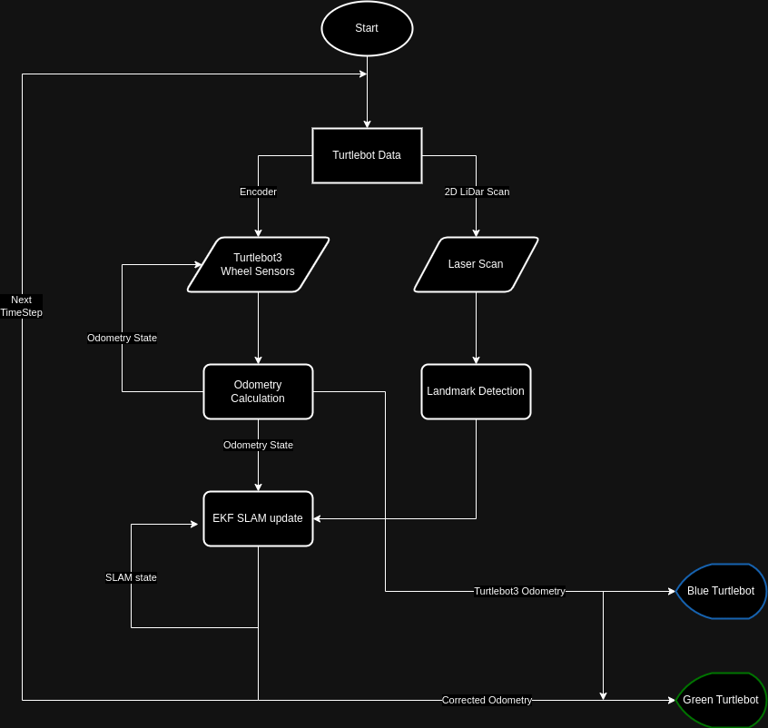
Software Structure
The overall structure of the project is shown in the flowchart below:
Odometry Model
To get the odometry from the wheel angle and velocity, it applied kinematics model from Modern Robotics to conduct the Forward Kinematics and Inverse Kinematics of the robot.
The geometry model of the robot can be present using \(H\) matrix.
\[\begin{align*} H(\theta) &= \begin{bmatrix} h_1(\theta) \\ h_2(\theta) \end{bmatrix} \\ h_i(\theta) &= \frac{1}{r_i \cos{\gamma_i}} \begin{bmatrix} x_i \sin{\left (\beta_i + \gamma_i \right )} - y_i \cos{\left (\beta_i + \gamma_i \right)} \\ \cos{\left ( \beta_i + \gamma_i + \theta \right )} \\ \sin{\left ( \beta_i + \gamma_i + \theta \right )} \end{bmatrix}^\intercal \end{align*}\]For the Turtlebot3, which is a diff-drive mobile robot. The parameters are defined as
So that \(H(0)\) can be calculated as
\[H(0)=\begin{bmatrix} -d & 1 & -\infty \\ d & 1 & -\infty \end{bmatrix}\]Where \(d\) is the one-half of the distance between the wheels and the \(r\) is the radius of the wheel.
Hence \(F\) matrix can be calculated by
\[F=H(0)^\dagger = r \begin{bmatrix} -\frac{1}{2d} & \frac{1}{2d} \\ \frac{1}{2} & \frac{1}{2} \\ 0 & 0 \end{bmatrix}\]Forward Kinematics
The forward kinematics is to find the tranform from current state to next state \(T_{bb'}\) given the change in wheel positions \(\left( \Delta\phi_l, \Delta\phi_r\right)\).
- Find the body twist \({\cal V}_b\) from the body frame of the current state to next state:
- Construct the 3d twist by
- Then, the transform from current state to next state \(T_{bb'}\) can be calculated by
Inverse Kinematics
Inverse kinematics is to find the wheel velocities \(\left(\dot{\phi_l}, \dot{\phi_r} \right)\) given the body twist \({\cal V}_b\).
The wheel velocities can be calculated as
\[\begin{bmatrix} \dot{\phi}_l \\ \dot{\phi}_r \end{bmatrix} = H(0){\cal V}_b = \frac{1}{r}\begin{bmatrix} -d & 1 & -\infty \\ d & 1 & -\infty \end{bmatrix} \begin{bmatrix} \omega_z \\ v_x \\ v_y \end{bmatrix}\]Since this robot is non-holonomic so that it cannot move sideways. Hence \(v_y=0\), then the wheel velocities \(\left(\dot{\phi_l}, \dot{\phi_r} \right)\) are:
\[\begin{align*} \dot{\phi}_l &= \frac{1}{r} \left ( -d \omega_z + v_x\right) \\ \dot{\phi}_r &= \frac{1}{r} \left ( d \omega_z + v_x\right) \\ \end{align*}\]SLAM Algorithms
There are two key algorithm implemented on this project, one is the Extended Kalman Filter (EKF) while another one is the Circle Fitting Algorithm
Extented Kalman Filter (EKF)
The EKF algorithm allows robot to localize itself using the poses of all detected landmarks relative to itself. It is done by conditional probability. The key idea of the algorithm is to compare the theoretical landmark poses due to the odometry and actual detected landmark poses. Then, it finds the pose with the highest probability given the pose from the last timestep. After that it will update the origin of the odometry so that robot will know its actual pose in the real world.
Circle Detection
Data Cluster
This part of the algorithm uses the Unsupervised Learning Algorithm to cluster the data points so that robot will know which data points come from the same landmark.
Circle Fitting
To find the location and size of the circle, it used the Supervised Learning Algorithm to calculate the centroid of the circle.
Data Association
The data association is used for robot to know the circle detected belongs to which landmark. Since robot need to compare the measurement of a landmark from its current state with its previous state.
Packages
nuturtle_description: Visualizing the pose of the turtlebot3 burgerturtlelib: Call customized library functions for kinematics and slam calculations.nusim: Simulate the turtlebot in the real world.nuturtle_control: Performing the turtlebot kinematics calculation and parsing the command sent to theturtlebot3.nuslam: Performs the SLAM algorithm for correcting the error odometry.